 |
| 1: 1 Gear |
Today we will learn about some
types of motor available in market and are used at different places. In last
post we learnt about the construction and working of a DC motor. Here we will
learn about geared motor, core-less motor and brushless motor. Before we start
with geared motor, let us know some basics of gears.
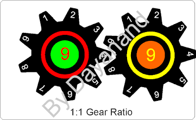
In this image there are two gears
having nine teeth each. In this case if left gear completes one revolution, the
right gear will also complete one revolution. This happens because each teeth
of left gear pushes one teeth of right gear. That means if one gear completes
60 revolutions in 1min. then the other gear also completes 60 revolutions in
1min. Hence in this scenario the speed ratio of each gear will be 1:1. The
other property of this type of gear assembly is that the torque or rotational
force in one gear is same as the other gear. Torque can be understood as a
force required for stopping a rotating object. To stop any object under motion
we need certain force opposite in direction and equal in magnitude to the force
generated by the object itself due to its motion. That means we can say the
rotating object is also generating a rotational force which we call as torque. Here
the torque generated by one rotating gear is equal to torque generated by other
gear rotated by first one. The unit of torque is Newton-meter.
 |
| 1:2 Gear |
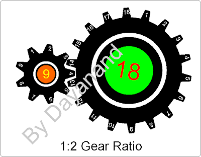
Now let us change the gear ration
as shown in next picture, left gear is having nine teeth but now right gear
with 18 and double the diameter of left gear. So here the gear ratio is 1:2. If
left gear completes one rotation, the right gear will complete half rotation.
Hence for the bigger gear to complete one full rotation, the smaller gear will
have to complete two full rotations. Hence we can say that if smaller gear
completes 60 rotations in 1min. the bigger gear completes 30 rotations in 1min.
i.e. speed ration of smaller gear to larger gear is 2:1. If we place a larger
third gear with 36 teeth after second one, then the speed of third gear will be further reduced by half. This is how we can use gears to reduce the speed
of a motor based on our requirement. The other aspect in this case is the
effect on the torque ration as mentioned in previous case. Here the ration of
diameter is 1:2, hence the torque is also doubled and as we keep on adding
larger gears the speed will keep decreasing in similar ratio, but the torque
will keep increasing.
Now if we reverse the scenario
i.e. large gear is rotating and forcing smaller gear to rotate, the smaller
gear will complete two rotations while the bigger gear completes one rotation.
That means in reverse direction speed will increase but at the same time torque
will decrease.
 |
| Geared Motor |
This is how we get so called
geared motors. The normal DC motors have higher RPM ranging from some thousand
to 50 thousands RPM also. At some application where we need very high speed, we
use normal motors, but in case we need lower operating speed like in robotic
application, we use geared motors. Such geared motor comes in various range of
speed starting from even 10 RPM to some hundreds of RPM. They also come in
various torque range based on different application requirement. It contains a
normal DC motor with a small gear box containing multiple chains of small and
big gears in it and the final output shaft is provided from gear box. So, here
we are not using the motor shaft directly to connect and load, rather the gear box
shaft is used as shown in picture.
The gears inside gear box can be
of plastic as well as metal. Normally plastic geared motor is used for hobby
applications with lesser load and metal geared motors are used for heavy and
robust applications. Plastic geared motors are cheap and can produce less
torque as plastic gears will damage at high torque and metal geared motors are
costly and can take heavy loads as gears are strong.
 |
| Core-less Motor |
Next type of motor is coreless motors. Its construction is same as normal DC motor except that the coil inside it is not winded on a metal core. There is a cylindrical cage type of construction is made with the insulated copper wire, which act as the coil. These motors come in very small size with length stating from 10mm and diameter starting from 4-5mm and speed in thousands of RPM. As we can see in picture, there is an outer metal casing, a cylindrical magnet which fits inside a hollow cage of copper coil with shaft connected to it. The working principal for core-less motor is also same as that of normal DC motor. Since there is no metal core attached to rotating shaft, hence the weight of shaft is less hence less electrical energy is consumed in such motors. Such low powered motors are used in very small toy applications such as micro helicopter toy or micro drones.
In all such DC motors, there is
always a rotating and a stationary contact to supply current to coil. This
contact wears out after long usage and start creating electrical spark between
rotating part and stationary brushes. These sparks start creating heat near the
contact and hence more wear and tear. To avoid such wear and tear we have next
type of motor that is Brushless motor.
 |
| Brushless Motor |
In a brushless motor we do not
have any rotating contact because the coil is stationary in it. As the picture
shows the coil is wound on a stationary iron core. This time we have three
different coils on three legs of core. One end of the coil is connected
together and the other end is used to supply DC input. That means here we have
three different inputs to provide DC supply which need to be provided in a
specific sequence. If we directly connect any two terminals to battery, it will
not work. The rotating part here is the top cover with attached shaft and a
circular permanent magnet inside its wall.
These motors draw a large amount of current, and the speed as well as torque of such motors is too high. The more the current a motor draws, the more electrical energy is consumed hence more mechanical power is generated. We need a specially designed motor driver for operating brushless DC motors and a specific type of digital signal as input to control the speed. These drivers provide output in form of pulses in specific pattern. As I mentioned, they need very high current, hence we need special battery also to operate these motors i.e. Li-Po (Lithium Polymer) battery. The motor, battery and the driver should be of matching rating to run the motor properly without damaging any one of them.
In case if we need to reverse the
direction of rotation we can interchange any two connection of driver’s output
connected to motor coils. These types of high speed motors are used in remote
controlled drones, helicopters and airplane. At this stage we will not go in details of
driver and input signals as it needs more understanding, hence it will be taken
up at some later stage.


1 Comments
Good Stuff
ReplyDelete