 |
| Capacitor |
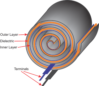
A capacitor works as a small reservoir to store
electric charge in it and provide small current in circuit whenever required.
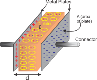
It can be also treated as a very small rechargeable battery. It’s a combination
of two metallic parallel plates separated by dielectric material between them.
The dielectric material can be ceramic, paper, mica, glass, distilled water,
dry air etc.
 |
| Capacitor Construction |
If a voltage is applied across a
capacitor, it charges it and the charge is stored till any load is connected
across it which can give a discharge path. There are broadly two types of capacitor
i.e. fixed capacitor and variable capacitor. Any capacitor has two
specifications i.e. its Capacitance in micro-farad (µf) and maximum voltage
which can be applied across it without destroying it. Capacitance shows how
much charge it can hold in it, larger the capacitance value, larger the charge
it can hold and vice-e-versa. So, any capacitor will have rating as 100 µf /
12V means we can apply a maximum charging voltage of 12V across it without
creating any defect. Usually we do not give full rated charging voltage; rather
for circuit design purpose we use half the rated voltage I.e. 6V in this
example.
 |
So, in a fixed capacitor, area of plates
and distance between the plates are fixed. But in variable capacitor, distance
between plates are fixed and one plate is fixed the other plate can be moved
from external shaft. As we rotate the
shaft of variable capacitor, the overlapping area of two plates varies which
changes its capacitance. Variable capacitors are used in radio receivers where
we manually tune the radio station by rotating the knob in front of it. Today in
age of digital music systems, these variable capacitors no more used.
Fixed capacitor can be divided further in
two categories, electrolytic capacitor and non-electrolytic capacitor. All electrolytic capacitors have polarity
marked on body. One terminal is mostly marked as Negative so the other terminal
should be considered as Positive. We should connect correct polarity of
capacitor in circuit else it will go defective. Electrolytic capacitors have
value starting from 1µf and above, and non-electrolytic capacitors have value
below 1µf. Also the non-electrolytic capacitors don’t have polarity, so any
terminal can be connected to any point in circuit. The symbol in circuit
diagram indicates where we need to connect positive and negative terminal. Non
electrolytic capacitor can have value as low a 1pico-farad which is equal to
1/1000,000,000,000 Farad.
 |
| Capacitor Symbol |
Now let us have a
look at this circuit, when switch S1 is closed, the loop-1 between cell,
resistor R1 and capacitor C is completed hence a current flow through resistor and
charges the capacitor. As the capacitor charges, the voltage across the
capacitor starts increasing and the moment the voltage across capacitor reaches
1.5V, the difference in potential between point A and B becomes same, the
charging current stops as current flow only if there is potential difference.
 |
| RC Circuit |
That means the flow of charging current through capacitor stop once the capacitor
is completely charged. Now let us switch off S1 and close switch S2, this
connects the load resistor R2 with capacitor and loop-2 completes and capacitor
finds a path to discharge it’s stored charge through resistor R2 hence the discharging
current flows through R2 until the capacitor is fully discharged i.e. the
potential difference between point A and B is equal I.e. 0V. You can see the
graph how voltage across capacitor increases while charging and how voltage
decreases while it discharges through R2. It neither charges linearly nor
discharges linearly that’s why the charge and discharge graph is also not
linear rather curve.
This charging and
discharging time T is time period if this charge and discharge cycle. The
higher there value of R1 and C, the longer is the charging time. Similarly,
higher the value of C and R2 the longer is the discharging time.
 |
| Charge-Discharge Graph |
Time of any resistor and capacitor circuit
can be calculated as t = R x C, where t is in second, R in Ohms and C in farad.
So, the charging time t1 = R1 x C and discharge time to = R2 x C. So total time
period if this circuit is T = t1 + t2 seconds. So, in any circuit if we want to
create a wave of time period of any value, we can decide value of Capacitor and
Resistor in circuit and get desired time period. We will see its use, when we make our blinking LED
circuit.
Parallel and series connection of Capacitors
Let us see what
happen if we connect capacitors in parallel and series, if there Capacitance
increases, decrease or remain same. The net Capacitance is sum of
 |
| Parallel Capacitor |
all
capacitors value connected in parallel, so it is reverse to parallel connection
of resistor. While connecting electrolyte
capacitors in parallel we should ensure to connect same polarity together, we
cannot reverse the polarity. For non-electrolytic capacitor we can ignore
polarity as they do not have polarity. So, net capacitance of parallel
connected capacitors is calculated as C = C1 + C2 + C3 + ……….+ Cn.
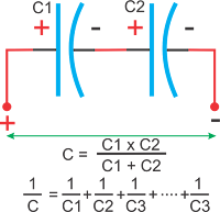
If capacitors are
connected in series, the net capacitance is lower than the
 |
| Series Capacitor |
Value is clearly mentioned on electrolytic capacitor; hence
it is easy to read. For non-electrolytic capacitor we should know how we can read
their value as their size is small and not easy to read. If it is written 1 or
1P, it means 1 Pico-farad. Similarly up to 100 or 100P means 100 Pico-farad. Above
that if we have 3rd digit other than ZERO, work as multiplier. For example,
102 means 10x100 = 1000pf = 1kpf. Similarly, if we have 104 mentioned on
capacitor, it means 10x10000 = 100,000pf = 100kpf can also be read as 100nf
(Nano-farad).
So, that’s all about capacitors, next we will learn about Inductors or Coils, keep watching.


0 Comments