 |
| LDR & Photo Diode |
 |
| LDR |
A commonly available LDR looks
like this having a small disc like shape, the two brown portions are very thing
metallic film acting as contacts and are connected to the two terminals. There is
a small gap between these two metallic films in snake like structure which
contains Cadmium Sulphide (CdS).
 |
| LDR Symbol |
LDR is normally connected in
series of a resistance, and either the voltage across LDR is measured by
circuit or voltage across the series. As the resistance of LDR changes due to
variation of light, the current through the series combination also changes.
This variation in current changes the voltage across LDR or the series
resistor, this variation is proportional to light falling on LDR hence by
measuring this voltage we can know the status of light around the LDR. This
sensor is commonly used in automatically switching on lights when it is dark
and switch off when its day time and sufficient light falls on LDR. In such
application, speed of switching operation is not much concerned as they have a
response time of some 10-100 milli seconds.
 |
| Photo Diode |
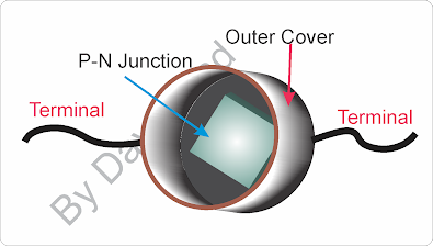
There is another light sensor
(photo sensor) called photo diode. It is a bulky component as it consists of a
casing with lens/light filter in front and a P-N junction diode inside casing.
Light is allowed to pass through lens or filter and falls on P-N junction diode
activating the diode to operate. Materials used for diode here is Silicon,
Germanium, Indium Galium Arsenide or Lead Sulphide.
 |
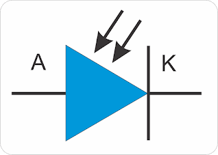
| Photo Diode Symbol |
In absence of light the
photo diode is inactive. Its working can be compared to that of LED, which
produce light in visible range when forward biased and the holes and electrons collide
with each other. On the other hand, a photo diode is always used in reversed
biased, hence no current flows through diode in normal condition. When light
falls at the junction of P-type and N-type material, the electrons are exited
and start moving and combining with holes near the junction. Reverse current
through diode directly proportional to light intensity falling on junction.
More the light intensity more is the reverse current and vise-e-versa.
 |
| Photo Diode Circuit |
Photo diodes can be operated in
two modes, one is reversed biased as we saw above and the other is in zero
biased condition, in which it acts like a small photovoltaic cell commonly
known as Solar Cell. Zero biased means no voltage is applied across the photo
diode. But when light falls on it, a forward current is generated inside it
flowing from Anode to Cathode. This flow of current generates a potential difference
across it with positive at anode and negative at cathode.
That’s all about basics of light
sensor or photo sensor, we will see their use in future posts when we will use
it to turn on and turn off light automatically based on surrounding light.
Further when we advance ahead, we will collect input with light sensor and
accumulate in micro-controller and also sending it to website over internet when
we will learn about making IoT (Internet of Things) project.


2 Comments
VERY GOOD STUFF
ReplyDeletefragciVrep_boBellevue Cody Bou https://wakelet.com/wake/vvQNxAXdfOz7Mmh02Xlrk
ReplyDeletesteatlomolin