 |
Let us learn about voltage
divider circuit which we will come across multiple times in future topics to
come. As the name suggests this type of circuit divides the supplied voltage
across it based on the value of resistance across it. In such circuits the resistors
are always in series. We can have all resistors in series or any other
component in series which can offer resistance or can create some voltage drop
across it, as we seen during calculation of LED circuit in previous
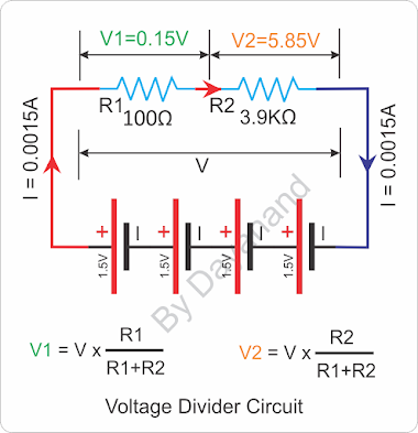
post. Refer the circuit where we have two resistors R1=100Ω
in series with R2 = 3.9KΩ = 3900Ω.
As we learnt in blog on under
series connection of resistors, the total resistor in this circuit will be R = R1
+ R2 = 100 + 3900 = 4000Ω.
Further we have connected four
cell in series so the total voltage V = 4 X 1.5V = 6.0V.
Based on Ohms law let us
calculate current in whole circuit as I = V/R = 6.0/4000A = 0.0015A.
Since both resistors are in
series, hence the same current will flow through both resistor, so again using
Ohms law let us calculate voltage across each resistors using v = i x r.
V1 = I x R1 = 0.0015 x 100 =
0.15V
V2 = I x R2 = 0.0015 x 3900 =
5.85V
As we divided voltage ‘V’ in ‘V1’
and ‘V2’ so let us adding V1 and V2 we get V = 0.15 + 5.85 = 6V, means the calculation
is correct.
Important point to note here
that voltage drop is higher across higher resistor and lower across lower
resistor, in series.
 |
This property is used in volume
controller of old audio amplifiers/music system as shown here. Now a days in
digital music systems, CD/DVD/BlueRay players these are not used, there the
signals are digitally multiplied or divided to increase or decrease the audio
level. As shown here if a voltage is applied across variable resistor across
point A and C, the voltage at top of resistor ‘C’ will be 3.0V, at bottom ‘A’
will be 0.0V and accordingly in middle it will be 1.5V (half of 3.0V).
If we measure voltage ‘V’ across
point ‘B’ and ‘A’ it will be minimum (0.0V) when the pointer is at bottom
because resistance between point ‘A’ and ‘B’ will be zero. As we move the
slider up, the resistance keeps on increasing hence the voltage drop ‘V’ keeps
on increasing and is highest when the pointer is at top i.e. 3.0V. This is how
the audio volume was used to change in old audio systems.
 |
| Voltage Divider |
We learnt in previous
posts that when a diode is forward biased, it conducts electricity at the same
time produce a voltage drop of 0.7V.
Here, the supplied voltage V is 6V
(4x1.5V) which drops against each diode in series as V1= 0.7V and V2 = 0.7V.
So
the balance voltage should be observed across resistor ‘R’ as V3 = V – V1 – V2
= 6 – 0.7 – 0.7V = 4.6V.
Now using ohms law we can calculate the current through resistor as I = V3/R = 4.6/330 = 0.0139A.
That’s all about voltage divider
circuit. This basic concept is in understanding basic of digital circuits in
future post. Hence it is suggested to have this concept crystal clear. For any
more clarity, you may leave your comments below which shall be addressed ASAP.
Keep watching for upcoming topics. You may also
follow us through email on the right hand side to get mail trigger once new
topic is posted.


0 Comments