Analog Signal:
We hear lot about digital
computer, digital watch Vs analog watch etc. around us. So what are these
analog and digital stuffs around us? Let us try to understand the basics first
so that it will be easy to understand these technologies in further topics. Though
there are many more components left to learn, we will cover them slowly as when
I will see the need to explain them. First we will see what is Analog voltage
or Analog signal, as this came first and then came the Digital technology.
 |
| Analog Signal |
Digital Signal:
 |
| Digital Signal |
So what is then a digital signal?
Opposite to analog signal, a digital signal will have only TWO values at any given point of
time. There cannot be any other voltage level in digital signal. It will be
either “High” or “Low”. High level is also referred as digital – ‘1’ and low
level is referred as digital – ‘0’. Refer the graph shown for a digital signal;
it has only two values i.e. either ‘5V’ or ‘0V’ at any given point of time. So any signal having precisely two voltage
levels ONLY at any given point of time can be considered a digital signal. Here
we shown two levels as 5V and 0V, there can be other levels also like 12V and
0V, 3.3V and 0V which we will see in different digital components or Integrated
Circuits in future topics. But one condition is same for all such different
signals, and that is they can have only TWO levels, no other level will be seen in digital
signals. ‘0V’ is always considered as
“Digital – 0” or “Low” and the other voltage level i.e. ‘3.3V’, ‘5V’ and ‘12V’
is always treated as “Digital-1” or “High”. Any digital computer can understand
only these two levels i.e. ‘0’ or ‘1’.
This number system of ‘0’ and ‘1’
is called as “Binary Number System”
as it has only two digits in this system and all other numbers can be formed
from these two digits also called as “Bits” in digital world.
We have seen in transistor and
MOSFET graphs that they have two region of operation. One is Ohmic region the
other is saturation region.
In case of analog systems,
transistors or MOSFETS are operated in Ohmic region hence based on different
level of input signals, there is different but amplified level of output
signal.
But in case of Digital systems, transistors and MOSFETS are always
used in Saturation and cut-off region, where the transistor or MOSFET is either
fully turned ON or is completely turned OFF.
 |
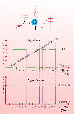
Look at the small MOSFET based
circuit and its related graph. In the circuit the position of switch is correlated
with digital-0 and 1. When the Switch is OFF, VG=0V hence this
position is take as “digital input-0” and when
the switch is ON, VG=5V which is taken as “digital input-1”.
- When input is ‘1’, the MOSFET is
turned ON and act as a Closed switch between
Source and Drain, hence the “Vout” is connected virtually to negative of
battery and hence Vout = 0V or Digital-0.
- When the input is ‘0’, the MOSFET
is turned OFF and act like an Open switch
and hence Vout = 5V or Digital-1.
In the graphical form same thing
has been shown, while the digital input is LOW (0) from 0 to 2 sec, the digital
output is HIGH (1). Similarly from 2 to 6 sec, the digital input is HIGH (1)
hence the digital output is LOW (0) and so on.
This is a sample digital circuit,
and actually an example of digital gate (NOT Gate) which we will see in more
detail when we will learn about other digital gates which are the building
blocks of any digital circuit.
So, as we saw digital signals
seems easy to understand as they have only two states “HIGH” and “LOW” and
Analog signals have infinite number of values at different point of time, hence
the graph seems complex. But it is not that, both have their own complications
when we start implementing them, but if we are able to understand the basic
concepts behind them it will be easier to handle both types of signals. In fact
analog signals are more interesting as we can modify the analog signals to get
different wave forms, but in case of digital signals, we have only one type of
waveform that is “Square Wave” or “Rectangular Wave” as we can see in the
graph.
So, you will be surprised that if
all computers work on digital platform, then how they are able to interact with
the variables around us which is completely analog in nature. The answer is we
have what is called “Analog to Digital Converter” and “Digital to Analog
Converter” circuits to interface analog world to digital technology and
vice-e-versa.
Will explain different types of
wave forms in upcoming posts hence keep visiting this space or subscribe over
email.


0 Comments