Header Ads Widget

How to make a wireless Oximeter?

#ESP8266 Project

During this Covid-19 pandemic oximeters are in high demand and so there are many different manufacturers making oximeter to supply in the market. At the same time many hobbyist are also searching on web how to make an oximeter at home itself. There are many circuits available on web which uses an Arduino board, a Max30100 series sensor and an OLED screen to display the values. Some are based on ESP8266 wherein the data is pulled on Blynk application etc. 

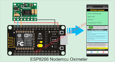
Here we will make an ESP8266 based oximeter using Max30102 sensor and an android application which can be installed on android mobile and data from sensor will be directly visible on your mobile phone via wi-fi link, no internet required. This makes it easier for patient’s family member to know his/her condition remotely within wi-fi range, without going near the patient. This is also an example of IoT(Internet of Things) implementation. You may check out this link for more detailed information on Internet of Things. Sample output on android application is shown here with connection diagram.

ESP8266 Oximeter

Let us see, how we can make this project and use at home. Being a homemade gadget we do not recommend using it for medical purpose though it shows almost same result as those cheaply available in market. This displays Oxygen level, average heart beat and temperature. 

Parts Required

  • ESP8266 NodeMCU board or ESP12 board
  • MAX30102 (heartbeat, oxygen and temperature sensor)
  • Android mobile (to load application)

Other one time requirements to program ESP are:

  • PC or laptop with Arduino ide application loaded
  • USB cable to connect NodeMCU to program

The arudino code can be downloaded from here
Or you may copy the complete code here and paste in Arduino application.


All the required libraries in the beginning of the code should be installed in arduino software which is installed in the PC.

“MAX30105.h” and “heartRate.h” are both included in “SparkFun_MAX3010x_Sensor_Library-master”. This library can be downloaded from github.com from this link - https://github.com/sparkfun/SparkFun_MAX3010x_Sensor_Library

Those who are new to arduino programming may checkout multiple tutorials available on web to setup arudino ide software and how to add new libraries in zip format. The ESP8266 NodeMCU consist of USB to serial converter chip (CP2102 or CH340/341) for which again we should have driver installed in PC so that nodemcu can get detected as a particular com port.


We can make this oximeter using NodeMCU (as shown in first diagram above) which is the easiest way as programming nodemcu is very easy as no additional external components are required.  Just plug the USB cable, setup the com port number in arduino ide software and upload the program. After programming only four connecting wires are required to connect the MAX30102 sensor module with ESP board i.e. +3.3V, Gnd, SCL and SDA. Rest all pins of sensor and ESP boards are to be left open. The ESP board gets the power from USB cable connected to it and PC. Once programmed, we can disconnect the USB cable from PC and connect to any mobile charger outlet having 5V output. 


How it works?

  • The ESP8266 board is programmed to work as mini web server in AP (Access Point) mode with SSID – “Oximeter” and password “12345678”.
  • The moment power is applied to ESP board, it runs the program loaded on it and the server and access point starts.
  • ESP board then initializes the sensor with set parameter to turn on Red LED and IR LED built in it. If the red LED in sensor doesn’t glow after 1-2 seconds of powering ON the setup, then there is some error. Check the connections and reset the ESP board or recycle the power source.
  • Once the RED light is visible on sensor, your hardware setup is ready with program loaded on it.

Now download the android application APK file from here and install on your mobile.

Switch on wi-fi on your mobile phone, you should be able to see wi-fi with SSID – “Oximeter”. Connect to it and when prompted for password, enter “12345678” and connect. The mobile will connect to this wi-fi with limited connectivity w/o internet as it is not required and not enabled in ESP8266.

Once connected to this wi-fi SSID, open the application on your mobile and you should get the output on screen as shown in below screen shots.


Types of message received on application.


ESP Oximeter Android Application

Message 1:Check Oximeter power and your wifi connection. For further help check below, “How to setup EspOximeter” – This error is received when no wifi or internet connection detected on mobile.

If the mobile is connected with any other connection other than “Oximeter”, then in this case you will get only white screen with no message.

Message 2:Finger not detected” – This message comes if all setup is OK, your mobile is connected with correct SSID and sensor is also active but unable to sense any finger on sensor.

Message 3:Reading data” – This means that the oximeter has sensed finger in front of it and is reading the data. Hold your finger stable on sensor for few seconds so that the reading is stabilized.
 
Here it will show oxygen level, average heart beat and your body temperature in Fahrenheit. The web server is programmed with small piece of java script so that it can keep sending real time data on screen automatically without refreshing the screen.

Note: In case the screen seems to be freez and not changing, you may click on refresh button and check again. Your ESP8266 based Oximeter is ready now.
 
ESP12 Programming

There is other smaller version of ESP8266 board i.e. ESP12 which can also be used to make this Oximeter as it has the SDA (Serial Data) and SCL (Serial Clock) pins. Only thing is that it requires additional setup for programming and running the device. There are many methods to program the ESP12 but I prefer below setup. 
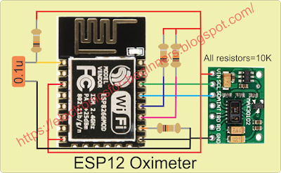
All additional components are required as shown in diagram so that the ESP12 module boots in flash mode. On the left we have ESP12 module and on right we have NodeMCU board. After making this temporary arrangement on breadboard, plug the USB cable on NodeMCU and program in the same way thru Arduino software. Code will be same for ESP12 also, without any change.

ESP12 Oximeter

Once programmed below setup can be used to run the oximeter, but care has to be taken to provide external regulated DC power supply of 3V to 3.6V, as ESP12 operates between these voltages. The sensor module can run from 1.8V to 5V hence 3.3V external supply will support both. Again few external components are required to be wired around ESP12 so that it can now boot from flashed program. All resistors are 10K 1/4 watt and capacitor is 0.1uf or 104. Capacitor is used here to give power on reset pulse to ESP12 board.

You may like to buy ESP8266 from here.

Buy MAX30102 sensor module from here.

And buy ESP12 module from here.


Return to List of content                                                Return to DIY Project List


Post a Comment

0 Comments