Colorful lights attracts every one, be it a kid or middle aged or old aged people. But based on age and mood our choices keeps changing. RGB lamps are good choice to select the color of lamp of your choice based on mood or time or any function. As we can set the color of our own choice and mood, hence this is also called "Mood Lamp". Since the different combination of Red, Green and Blue lights can create any color of visible spectrum, hence these lamps are best to select color of your choice. Here I am presenting a design of RGB lamp or mood lamp which can be controlled through a mobile application over wi-fi without internet. It is one of the applications of IoT (Internet of Things).
 |
The lamp act as an wireless access point (AP) based on ESP01 module and connects with your mobile. The android application allows to select different modes to control the lamp color and choose color of your choice. Apart from manual color selection, there are some modes to select from like flasher mode, auto color change mode, single color etc.
Parts Required:
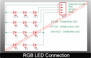
The circuit diagram is shown below. I have used pair of BS170 low power mosfets to drive each LED leg whose connection diagram is shown in next diagram. Although single BS170 is capable to drive string of each color LED, still I have used two in parallel to avoid heating over long run. For resistance 'R8', I have used 12Ω + 4.7Ω in series to get 16.7Ω.
The code is written in Arduino as below.
Program the ESP 01 with above Arduino code and connect the parts on general purpose board or you may create PCB as suggest below.
For preparing the base of LEDs, I have taken tin lid of paint box, you can take any circular metallic base. Clean the surface with sand paper. Make holes to pass the wires for common anode and individual color LED wires. Solder each color LED is series and take the final output wire for connecting to circuit. You may use some glue to fix the LED heat sink on the metallic base. It will be better if you use dual sided tape which comes for heat sinks.
Make some arrangement to fix the PCB and 12V DC adapter in the base and connect the LED base wire to controller PCB. Solder long wire at the AC input side of 12V adapter and take out from hole in PVC pipe to power the light. To make diffuser you can use diffuser from any old defective high power LED lamp as per size to cover your LED assembly. I have used a milky plastic food container here as it fits and work properly for me. I have made few small pin holes on top of my diffuser as my LED base was heating up as hot air inside it was trapped and made it hot in long run. With only three pin holes this issue was resolved.
Once hardware setup is done, download the android application from here and install on your android phone.
There are three screens in this application, one is home screen, second is setting screen and third is help screen as shown below. Help screen guide you how to setup the application and connect with RGB lamp.
If you click "Clear" in setting screen, any stored IP will be deleted from application.
Power ON the mood lamp/RGB lamp, it will start operating in default color change mode i.e. RGB flash and fade mode.
Switch ON the wi-fi on your mobile, you should see new AP named "Mood_Light", connect to it. You may change the name in Arduino code if you wish.
It will ask for password, enter "12345678" as we have set in Arduino code. You may change password of your own choice in code itself before programming the ESP 01 module.
Once connected, comeback to home screen and start enjoying your mood lamp.
There are multiple options to choose from:
1- Select individual color that is Red, Green or Blue
2- Select Auto color change mode which has four sub modes
i - Slow Auto Color change mode - Color automatically change to whole spectrum mixing individual colors through cycle very slowly.
iii - RGB Mode - Each color fades in and fades out and then flashes in cycle.
3- This is manual color selection mode. Drag the black ball in the color window of application to select the color of your choice. The RGB value of selected screen color is displayed in the "Color Value" field below color canvas.
Watch out the video to get the idea how it works.


0 Comments